Concept and Purpose
Concept and Purpose
Prototype track layouts have been replicated
in most locations, and the sequence and (as much as possible) the spacing of prototype locations
has been preserved -- although highly compressed. The main area of compromise was between Mt. Pocono
and East Stroudsburg. In order to increase the local industry switching available on the model,
I decided to include East Stroudsburg just before the entrance to the Croxton Staging Yard (east end
staging). Unfortunately, that location is around the corner from Mt. Pocono, while the prototype
requires about 18 miles -- much of it downgrade -- to cover that distance. The added operating interest
of the local switching at East Stroudsburg outweighs the loss of prototype fidelity, however.
The Bloomsburg Branch is modelled on the lower level, although the modelled section from
Taylor to Rupert is drastically compressed.
Before starting the track plan, several specifications were established for physical characteristics of
the railroad. The base elevation -- at Scranton City Yard -- was set at 50" from the floor. Although
Rupert is lower, and the upper deck is considerably higher, this was the starting point. The minimum
mainline radius is 30" and the minimum mainline turnout is #8, with #6s used in the yards and industries.
Grades vary across the railroad, but outside the helper district, the maximum is 1.5%.
Experimentation showed a "standard" train length of 15 feet, including the motive power and caboose,
to be ideal. At 15 feet the train is long enough to extend around a bend or through a scenic element
(stand of trees, cut, etc) so it appears to go out of sight. Most trains are at least 20 cars in length,
but certain trains are considerably longer, and some much shorter -- it varies quite a bit according to
traffic levels.
Spacing of the towns was determined in part using the 15-foot trainlength. Other factors considered were
the actual distance between the prototype towns and what work a train might be expected to perform in the town.
Staging consists of three hidden staging yards: 11-track yards at the eastern (Croxton) and western (Binghamton) ends of the mainline, and one 7-track staging yard (Northumberland) west of Rupert on the Bloomsburg Branch, representing the remainder of the Branch and the Reading Railroad. Three single-track staging "yards" connect at City Yard (representing the Diamond Branch), the west end of Taylor Yard (representing the D&H interchange), and at Pittston Junction (representing the Lehigh Valley interchange).
The model is located
in a basement approximately 28 feet by 34 feet, with the usual basement appliances
to work around. Although the ceiling is fairly high, the central beam and
heating duct prevented me from fitting a mushroom into the space, so we settled
on a double-deck layout. The track plan is a relatively simple walk-around
plan with one central peninsula and staging at either end of the visible portion
of the railroad.
This plan allows the inclusion of much of the Bloomsburg Branch and the Main
Line from Scranton to Mount Pocono, with East Stroudsburg added at the end.
There is about a 45 foot run between Scranton City Yard and Taylor Yard, allowing
a significant run between yards. Through trains drop and pick up cars at City
Yard, while classification and most switching is done at Taylor, as the prototype
did. Transfer runs between the two yards occur throughout the day, and help
keep the Taylor Yardmaster out of mischief. And, of course, the transfer runs
are exactly right for the Overland EL transfer caboose!
The modelled Main Line is about 325 feet long, and the Bloom is about 160
feet long. The Main Line grade begins in Scranton yard and continues to Lehigh
Summit, reaching a maximum of 3.5% but remaining about 2% for most of that
distance. We were able to imitate the profile of the prototype, though the
grades have been exaggerated for operational interest. As on the prototype,
though, there is a stretch of level track through the Nay Aug tunnel to challenge
the train crews! The heavy trains and steep grades challenge the crews and
the trains actually need the helpers to get up the hill.
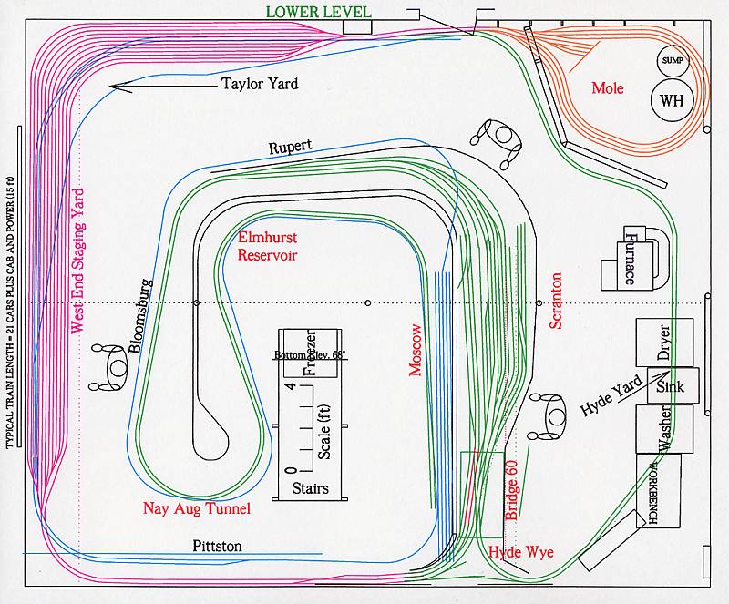
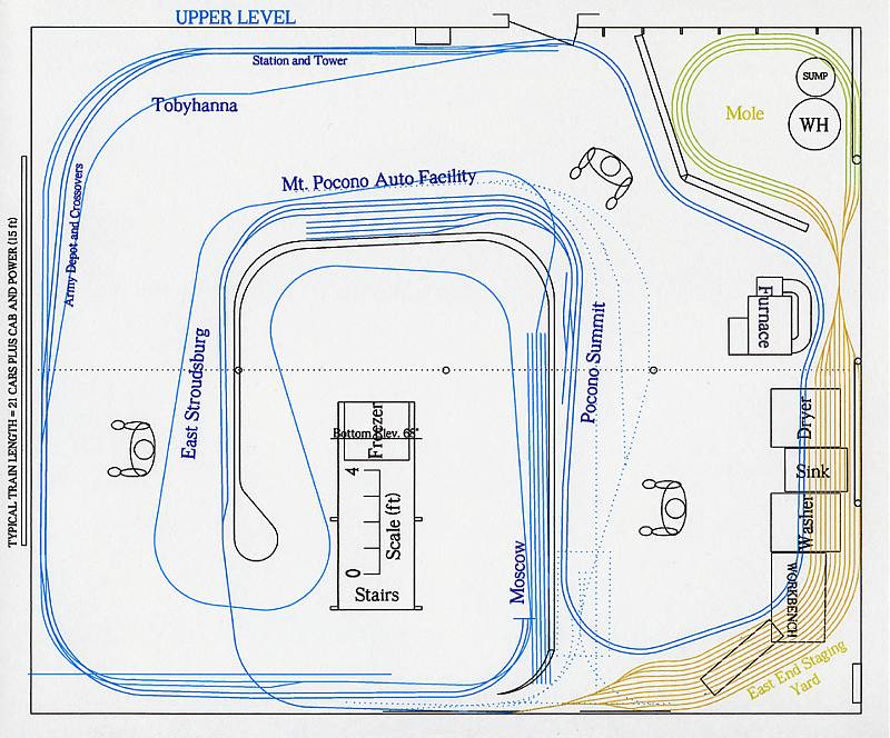
The plans below show the general mainline layout of the mainline and branch.
In some areas local spurs are detailed but the local track arrangements were
adapted to the space available using prototype track plans as a guide after
the mainline was built. Since plans for a double-deck layout can be confusing,
I've included separate figures showing the Lower and Upper Levels, with the
Bloomsburg branch and staging yards shown in different colors. Town name colors
indicate mainline, branch, or staging. In the Upper Level figure, some Lower
Level features (like Taylor Yard and the outline of the Branch under East
Stroudsburg) are shown to help illustrate their relative positions.
Also note that the plan includes a "mole" position. We constructed the layout
in stages, and started operations before the Mole had been built. I therefore
found that to restage the railroad, all that is necessary in the staging yards
is to swap the power and caboose, and turn the waybills. Because of the way
trains were working in Scranton, the west end of the train was always the
block worked -- on both eastbound and westbound trains.
So, we decided not to build and use the Mole, and extended the Upper (Croxton)
Staging Yard behind the furnace and to the wall beyond the water heater. This has proven to be a
very good change because Croxton was not a very large yard and severely
limited train lengths. Now train lengths are controlled by traffic
levels and more trains can be long enough to require helpers -- as did
most non-TOFC trains in 1975. Next step is to replace the yard throat,
which was originally built as a compound ladder using 3-way turnouts to save space,
with a longer one utilizing a simple ladder and #8 turnouts. Hopefully that will eliminate the
operational issues caused by the interaction of the 89-foot TOFC flats, autoracks, and
other long cars with the unfortunate geometry of the 3-way turnouts.
Model Locations
Follow the links
below to pictures of individual towns or areas of the layout.
"Station Name" links are to information about the prototype location
being modelled.
Unfortunately,
I have not yet fleshed out all the pages. Please excuse the blank pages
and try back again later if you go to an unfinished page. Thanks!
In the Table, the modelled portion of the railroad has white text and borders, and the links are to location details and "Model" links you to the page for the modelled town.
|
|
|
|
|
| |
|
|
Model |
| |
|
|
|
| |
|
|
|
| |
|
|
Model |
| |
|
|
Model |
| |
|
|
Model |
| |
|
|
Model |
| |
|
|
Model |
| |
|
|
Model |
| |
|
|
Model |
| |
|
|
Model |
| |
|
|
|
| |
|
|
|
| |
|
|
|
| |
|
|
|
| |
|
|
|
| |
|
|
|
| |
|
|
|
| |
|
|
|
| |
|
|
Control
A walk-around
layout almost demands a form of command control, where each locomotive carries
a decoder and can be controlled independently from other locomotives on
the railroad. A walk-around layout also practically demands a wireless control
system to allow operators the freedom to concentrate on their train and
not the location of the next control plug. I selected North
Coast Engineering's (NCE's) Digital Command Control (DCC) system based primarily on its ease of
use and flexibility. At the time I selected it, they were also one of the
few systems offering wireless (radio) throttles. among the other attractive
features of the NCE system were the ability to set up locomotive consists
that could be addressed by the lead or trailing unit numbers (rather than
by a "Consist Address"), the duplex radio system (which confirms that the
system received the throttle commands), and their small, easy-to-use handheld
radio throttles.
Recent developments in decoder features and throttles, however, have driven
us to change from the NCE throttles (although the underlying DCC system is still NCE)
to the ProtoThrottle,
a portable radio throttle designed to resemble a diesel engine control
stand. The ProtoThrottle incorporates an eight-notch throttle lever, a three-position
reverser, a variable-rate brake lever, horn lever, bell control, and several
other, configurable, controls.
|
|
The ProtoThrottle
is made most effective by the inclusion of brake functions in many of the
newer decoders. Combined with the momentum already included in the decoders,
the locomotive can be configured to coast quite a distance when the throttle
is closed, and the brake can be configured to stop the locomotive in a variable
distance, depending on the programmer's wishes. I have standardized on SoundTraxx
decoders, both motor-only and sound, and have them set up with the maximum
decelleration momentum. Starting momentum is much less, but the train weight
helps to moderate jack-rabbit starts. The brakes are adjusted to stop the
train in a reasonable distance, but definitely not on a dime! The result
of these settings is that the engineer starts the train relatively slowly
and, when he needs to stop he closes the throttle and lets the locomotive
coast until he needs to apply the brake to stop. Meanwhile, the prime mover
sounds have gone back to idle and the locomotive or train coasts along at
idle. It's a lot of fun!
Of course, because the engineer now has a lot more to do to control the train,
he doesn't have time to handle car cards or switch lists, or to plan switching
moves, so every train that does more switching than a block-swap at Scranton
gets a two-person crew.